")
|
Fender 5D4 schematic and layout. |
Building an amp based on the Fender 5D4 SuperStep 1 - The circuit BoardI had a few days off and it rained so I spent some time in the basement building an amp based on the Fender 5D4 Super circuit. I made the circuit and now I need another rainy day to make the chassis. There are a few good reasons to choose the 5D4 as a first amp DIY project. First, there is a low component count. This keeps it cheap. Second, there is only one stage of preamp. This makes it perfect for harmonica and very resistant to feedback. Third, the inputs go to separate preamp tubes and this allows you to set up the amp with a 12AX7 in one position and a 12AU7 in another and have really two amps in one chassis. The Super amp and the Pro amp (same circuit, different number of speakers) are similar to the very popular Bassman amp. They are very simple amps and are good for bass, harp or accordion. Building the amp requires finding the parts and soldering them together.
The skill set is not complex and anyone who built a model car from a kit
can put together an amp. The cost is very cheap compared to buying a new
amp. The results are amazingly good.
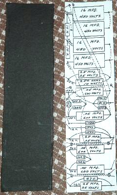
I cut a piece of heavy cardboard to the same size and I glued the layout to the cardboard. Fender used a thin fiber board. I used the thick cardboard that is used in cars to firm up the seats. I got it from a wreck at a junkyard. It is treated with plastic so it doesn't get mildewed or absorb water. You can use the stiff cardboard from a shoe box or even from a manila folder. Stiffer is better, but thicker gives you problems. Don't use plastic that will melt. I glued the circuit to the carboard with a few drops of Elmer's. You don't need to use much glue, just enough to hold it in place while you add the eyelets. By having the circuit layout right on the circuit board, it makes it very very simple to assemble the circuit.
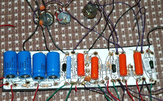
The eyelets cut the hole in the cardboard with their sharp edges. There is no need to cut or drill the hole.. The eyelets solder nicely. Tandy did not have 1/8 inch eyelets and I think that the 3/16 are a little larger than is needed. When I do this again I will use the 1/8 inch eyelets for most of the holes and the 3/16 or even 1/4 inch eyelets for the holes in the board that are not soldered, but are there to for wires to pass through the circuit. You don't really need the eyelets. They make it neat and they provide a way of easily replacing blown parts. You can just poke holes in the board and twist the leads together and bending them over on the back to keep them in place. Part of the advantage, though, of using the eyelets is that you can pull a bad resistor or recap the board without having to cut leads or unwind the twisted leads. Be very careful, especially with the larger eyelets that there is plenty of space between the eyelets. The higher voltage points might arc if the eyelets are too close together. Also, the cardboard might "carbonize" providing a conductive path from eyelet to eyelet. That's one reason I like the cardboard sealed with plastic from the wrecked cars. I bought the components from Mouser and Electronics Gold-Mine. The resistor kits at electronics goldmine had all of the resistors except for one. I bought the 1 watt assortment. The 1 watt resistors are a bigger, easier to see and work with and can take more abuse than the smaller resistors. 1 watt resistors are the exact same value, but they can take more power. Electronically they do not change the circuit. The 16 mfd electrolytic caps can be replaced with 20 mfd without any real difference. You might get a very slight boost in power from the amp. The 25/25 caps can be replaced with 50 mfd without any difference in performance, so use what you can find. The small .0005 and .0001 microfarad small caps are the same as 500 and 1000 picofarads. The catalogs use picofarads as the unit. The old fender layout is unreadable in the values of these caps and I screwed up by trusting the layout without referring to the circuit. I had to go back and unsolder the caps and put in the correct ones - so be very careful! The .05 orange drop caps (coupling caps) can be replaced with .1 mfd. For harp players and bass guitar players this will let a little more bass into the amp. It is a minor change and hardly noticeable, but it does help when you are trying to play amplified harp. Next place all of the components on the board. Don't twist the leads together. You want this to be easy to unsolder in case you make a mistake or a part fails. Use 20 gauge stranded wire (I don't like solid wire - it is less flexible.) You can use 22 gauge for the lower voltage wires (connections to pots and inputs). You might want to use coax on the input wires as this might be a source of hum. This should not be a problem because the wires are short and inside the chassis. There are several wires (dotted lines) that connect on the back of the board and there are several wires that are threaded through eyelets, but are not soldered. The leads from the guitar jacks go through the circuit board to the preamp tubes, but the circuit board is just there to organize the wires and keep the amp from being a bowl of spaghetti. The minus side of the big caps goes to ground. Use more ground wires that the circuit layout indicates. More grounding is better. The grounds attach to the chassis and the chassis is the ground, but a poor path to ground or a small resistance in the ground might add hum. I made all the ground wires black and I used what was available for the other wires. I should have come up with some kind of scheme to use meaningful color codes, but I was rushing towards the end. Wire the pots, too. Use sandpaper to rough up the back of the pots and solder a wire for the ground to the back of the pots and the tone cap is soldered to the back of the pot. In my last project, these solder points kept popping off because I used a low wattage soldering gun. I eventually wired all of the pot grounds to wires and using the Star philosophy, all the grounds from the tubes and circuit and pots met at one common solder point. My first amp had a slight hum anyway. That will be the subject of another page though. I make all the wires too long. It is easier to shorten them than it is to make them longer. I will snip them shorter when I solder them to the tube sockets. The picture below shows how the circuit board looked after I soldered all the eyelets and trimmed the leads. I used a 5 watt 470 ohm resistor (all the way to the right) because it is what I had on hand. I slipped and burned the paper in a couple of places.
I might be able to build the chassis on my next day off, so watch out!
|
|
 The
way that I do it is to to size a copy of the circuit from the fender layout.
I don't have an original to measure, so I sized the image to fit the components.
The circuit is 10 inches by 2-3/4 inches.
The
way that I do it is to to size a copy of the circuit from the fender layout.
I don't have an original to measure, so I sized the image to fit the components.
The circuit is 10 inches by 2-3/4 inches.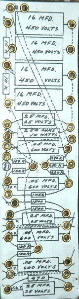 I
used 3/16 inch brass finish eyelets. I just put them in place and used
a hammer to tap them in place. I am considering buying the expensive eyelet
setter tool for the next project.
I
used 3/16 inch brass finish eyelets. I just put them in place and used
a hammer to tap them in place. I am considering buying the expensive eyelet
setter tool for the next project.